
TM 5-2410-240-23-3
0229
INSTALLATION
000229
N OT E
Install electrical connectors as tagged during removal.
Install tiedown straps as noted at removal.
1. Install wiring harness (Figure 16, Item 5) and grommet (Figure 16, Item 6) on machine.
2. Connect wiper motor connector (Figure 16, Item 1) on wiring harness (Figure 16, Item 3).
3. Install tiedown strap (Figure 16, Item 8) on wiper motor (Figure 16, Item 7).
4. Install wiring harness (Figure 16, Item 3) and tiedown strap (Figure 16, Item 4) to cab (Figure 16, Item 2).
N OT E
Install electrical connectors as tagged during removal.
Install tiedown straps as noted at removal.
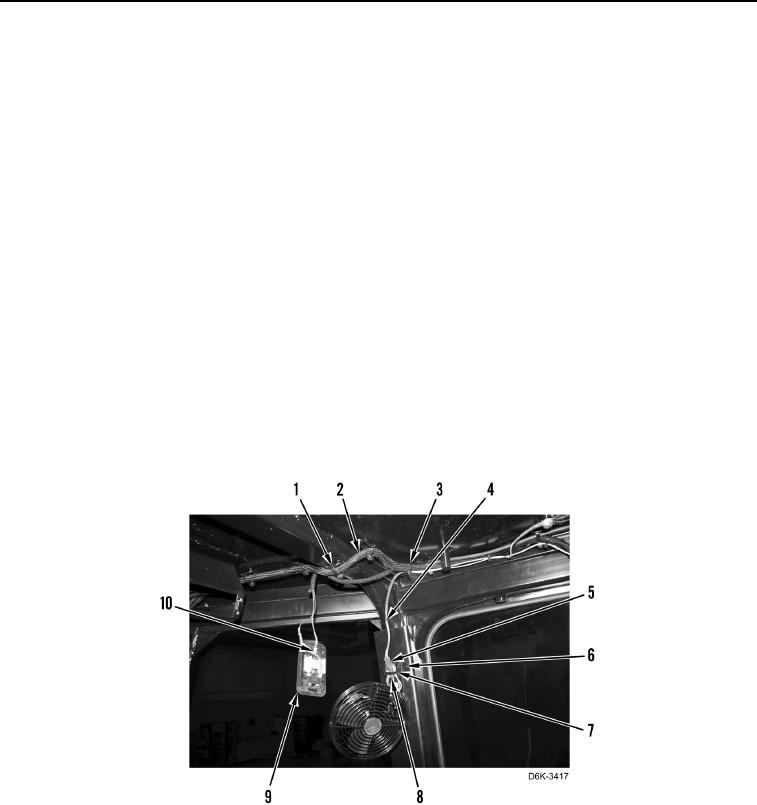
5. Connect two cab interior light connectors (Figure 17, Item 10) to cab interior light (Figure 17, Item 9).
6. Connect cab fan connector (Figure 17, Item 8) to wiring harness (Figure 17, Item 5).
7. Install tiedown strap (Figure 17, Item 7) and wiring harness (Figure 17, Item 4) to cab fan mounting bracket
(Figure 17, Item 6).
8. Install wiring harness (Figure 17, Item 2) and eight tiedown straps (Figure 17, Item 1).
9. Install wiring harness (Figure 17, Item 4) and tiedown strap (Figure 17, Item 3).
Figure 17. Cab Fan and Interior Light Connections.
0229