
TM 5-2410-240-23-3
0229
INSTALLATION CONTINUED
N OT E
Install electrical connectors as tagged at removal.
Install tiedown straps as noted at removal.
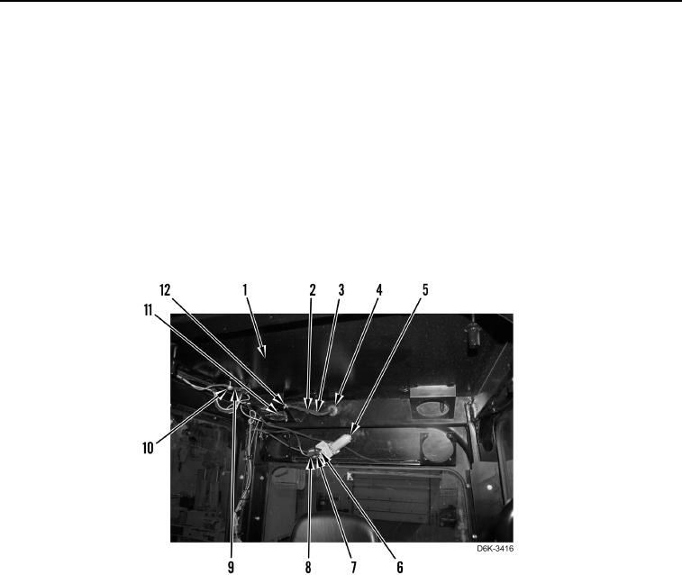
10. Install grommet (Figure 18, Item 4), wiring harness (Figure 18, Item 3), and two tiedown straps (Figure 18,
Item 2) to cab (Figure 18, Item 1).
11. Install five ground wires (Figure 18, Item 9) and bolt (Figure 18, Item 10) to cab (Figure 18, Item 1).
12. Connect two cab fan resistor wires (Figure 18, Item 11) to cab fan resistor (Figure 18, Item 12).
13. Connect rear wiper motor connector (Figure 18, Item 6) to wiring harness (Figure 18, Item 8).
14. Install wiring harness (Figure 18, Item 8) and tiedown strap (Figure 18, Item 7) to wiper motor (Figure 18,
Item 5).
Figure 18. Cab Wiring Harness - Rear.
0229