
26
TM 5-2410-240-23-3
FIELD MAINTENANCE
-
LEFT JOYSTICK SUPPORT SERVICE
0
237
Removal, Disassembly, Cleaning and Inspection, Assembly, Installation
INITIAL SETUP
References
Tools and Special Tools
0
0
Tool Kit, General Mechanic's
0
(WP 0289, Item 51)
0
Equipment Conditions
0
Screwdriver, Attachment, Torx, 1/4" Drive,
Machine parked (TM 5-2410-240-10)
T-27 (S0287) (WP 0289, Item 53)
0
0
Screwdriver, Attachment, Torx, 3/8" Drive,
Drawings Required
0
T-40 (S0289) (WP 0289, Item 53)
0
TM 5-2410-240-24P, Figure 112
0
Materials/Parts
0
Estimated Time to Complete
0
Rag, wiping (WP 0290, Item 21)
0
1.5 Hr
0
Tag, marker (WP 0290, Item 30)
0
Tiedown strap (WP 0290, Item 31)
0
Seal (2)
0
REMOVAL
000237
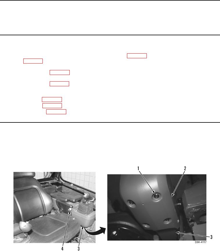
1. Press joystick control release button (Figure 1, Item 4) and slide joystick control support assembly (Figure 1,
Item 3) forward.
2. Remove four screws (Figure 1, Item 1) and cover (Figure 1, Item 2) from joystick control support assembly
(Figure 1, Item 3).
Figure 1. Joystick Cover - Lower.
0237