• Home
  • Download PDF
  • Order CD-ROM
  • Order in Print
Figure 5. Joystick Control Support Assembly Mounting Bolts.
Figure 8. Joystick Control Mounting Bolt.

Field Maintenance Manual 3 D6K Dozer Type I With Winch and Type II With Ripper
Page Navigation
  635    636    637    638    639  640  641    642    643    644    645  
img
.
TM 5-2410-240-23-3
0237
DISASSEMBLY
000237
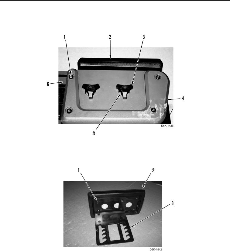
1. Remove four screws (Figure 6, Item 1), two adjustment knobs (Figure 6, Item 3), washers (Figure 6, Item 5),
armrest (Figure 6, Item 2), and cover (Figure 6, Item 4) from support (Figure 6, Item 6).
Figure 6. Joystick Control Support Cover.
0237
2. Remove four screws (Figure 7, Item 1) and armrest (Figure 7, Item 2) from bracket (Figure 7, Item 3).
Figure 7. Joystick Control Support Armrest.
0237
0237-5


Privacy Statement
Press Release
Contact

© Copyright Integrated Publishing, Inc.. All Rights Reserved.