
TM 5-2410-240-23-3
0237
DISASSEMBLY CONTINUED
000237
11. Remove bolt (Figure 16, Item 1) and bracket (Figure 16, Item 2) from support (Figure 16, Item 3).
Figure 16. Joystick Adjustment Lever and Bolt.
0237
N OT E
Upper and lower adjustment rods are not interchangeable. Upper adjustment rods have
notches for adjustment.
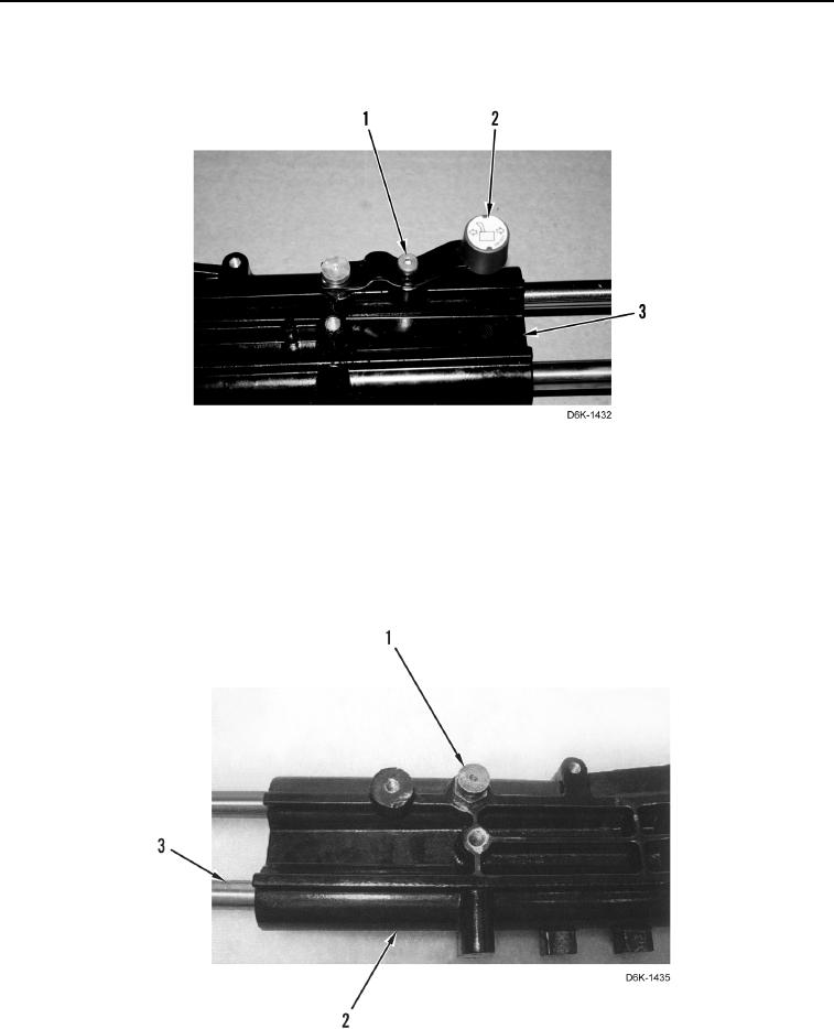
12. Remove pin (Figure 17, Item 1) and two adjustment rods (Figure 17, Item 3) from support (Figure 17, Item 2).
Figure 17. Adjustment Rods and Pin.
0237