• Home
  • Download PDF
  • Order CD-ROM
  • Order in Print
Figure 16. Joystick Adjustment Lever and Bolt.
Figure 20. Support Arm, Housing, and Pin.

Field Maintenance Manual 3 D6K Dozer Type I With Winch and Type II With Ripper
Page Navigation
  641    642    643    644    645  646  647    648    649    650    651  
img
.
TM 5-2410-240-23-3
0237
DISASSEMBLY CONTINUED
000237
N OT E
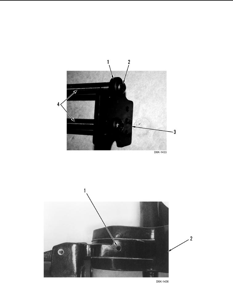
Note position of bracket before removing.
13. Remove two screws (Figure 18, Item 2), washers (Figure 18, Item 1), and bracket (Figure 18, Item 3) from
adjustment rods (Figure 18, Item 4).
Figure 18. Joystick Control Mounting Plate.
0237
14. Remove set screw (Figure 19, Item 1) from housing (Figure 19, Item 2).
Figure 19. Support Housing Set Screw.
0237
0237-11


Privacy Statement
Press Release
Contact

© Copyright Integrated Publishing, Inc.. All Rights Reserved.