
TM 5-2410-240-23-3
0237
DISASSEMBLY CONTINUED
000237
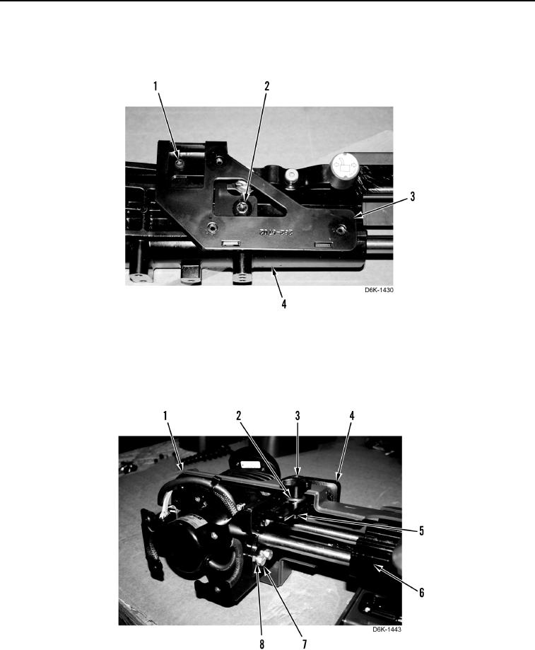
7. Remove two screws (Figure 12, Items 1 and 2) and bracket (Figure 12, Item 3) from support (Figure 12,
Item 4).
Figure 12. Joystick Bracket.
0237
8. Remove adjustment knob (Figure 13, Item 3), washer (Figure 13, Item 2), wrist pad (Figure 13, Item 4), four
bolts (Figure 13, Item 7), washers (Figure 13, Item 8), bracket (Figure 13, Item 5), and joystick control support
assembly (Figure 13, Item 1) from support (Figure 13, Item 6).
Figure 13. Control Support Assembly, Bracket, and Bolts.
0237