• Home
  • Download PDF
  • Order CD-ROM
  • Order in Print
Figure 6. Joystick Control Support Cover.
Figure 10. Joystick Cushion and Cover.

Field Maintenance Manual 3 D6K Dozer Type I With Winch and Type II With Ripper
Page Navigation
  636    637    638    639    640  641  642    643    644    645    646  
img
.
TM 5-2410-240-23-3
0237
DISASSEMBLY CONTINUED
000237
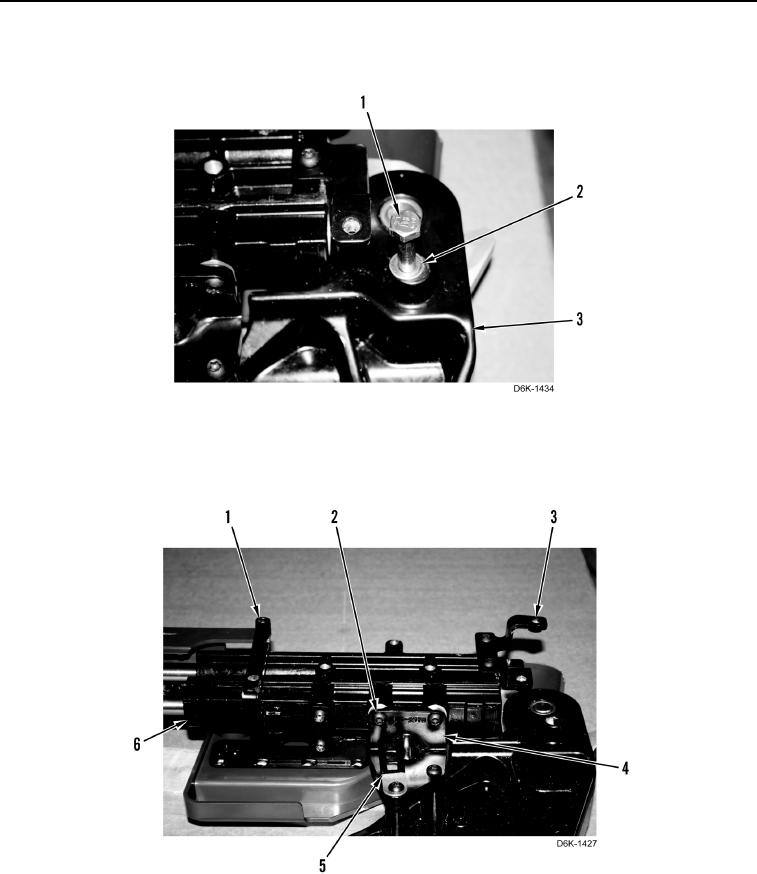
3. Remove bolt (Figure 8, Item 1) and washer (Figure 8, Item 2) from support (Figure 8, Item 3).
Figure 8. Joystick Control Mounting Bolt.
0237
4. Remove eight screws (Figure 9, Item 2), three mounting brackets (Figure 9, Items 1, 3, and 4), and clamp
(Figure 9, Item 5) from support (Figure 9, Item 6).
Figure 9. Joystick Control Mounting Brackets.
0237
0237-6


Privacy Statement
Press Release
Contact

© Copyright Integrated Publishing, Inc.. All Rights Reserved.