• Home
  • Download PDF
  • Order CD-ROM
  • Order in Print
Figure 27. Joystick Control Mounting Plate.
Figure 29. Joystick Adjustment Lever and Bolt.

Field Maintenance Manual 3 D6K Dozer Type I With Winch and Type II With Ripper
Page Navigation
  674    675    676    677    678  679  680    681    682    683    684  
img
.
TM 5-2410-240-23-3
0238
ASSEMBLY CONTINUED
000238
N OT E
Install adjustment rods as noted during removal.
Upper and lower adjustment rods are not interchangeable.
Upper adjustment rods have notches for adjustment.
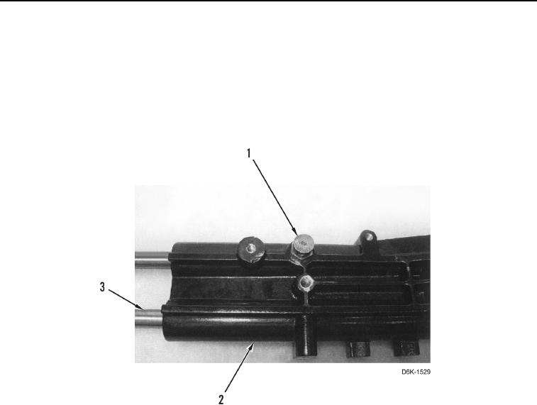
7. Install adjustment rods (Figure 28, Item 3) and pin (Figure 28, Item 1) on support (Figure 28, Item 2).
Figure 28. Adjustment Rods and Pin.
0238
0238-18


Privacy Statement
Press Release
Contact

© Copyright Integrated Publishing, Inc.. All Rights Reserved.