
TM 5-2410-240-23-3
0238
ASSEMBLY CONTINUED
000238
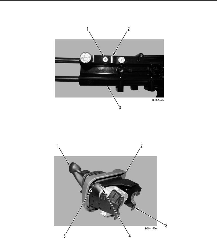
8. Install bracket (Figure 29, Item 2) and bolt (Figure 29, Item 1) on support (Figure 29, Item 3).
Figure 29. Joystick Adjustment Lever and Bolt.
0238
9. Install cover (Figure 30, Item 2), four screws (Figure 30, Item 5), joystick control assembly (Figure 30, Item 1),
and four new locknuts (Figure 30, Item 4) on bracket (Figure 30, Item 3).
Figure 30. Joystick Control Assembly, Cover, and Bracket.
0238