• Home
  • Download PDF
  • Order CD-ROM
  • Order in Print
Figure 37. Joystick Control Mounting Bolt.
Figure 40. Joystick Control Support Assembly Mounting Bolts.

Field Maintenance Manual 3 D6K Dozer Type I With Winch and Type II With Ripper
Page Navigation
  680    681    682    683    684  685  686    687    688    689    690  
img
.
TM 5-2410-240-23-3
0238
ASSEMBLY CONTINUED
000238
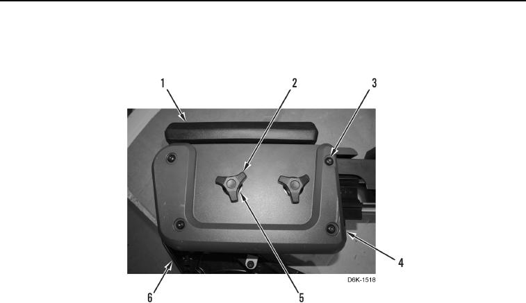
18. Install cover (Figure 39, Item 4), armrest (Figure 39, Item 1), two washers (Figure 39, Item 5), adjustment
knobs (Figure 39, Item 2), and four screws (Figure 39, Item 3) on support (Figure 39, Item 6).
Figure 39. Joystick Control Support Cover.
0238
END OF TASK
0238-24


Privacy Statement
Press Release
Contact

© Copyright Integrated Publishing, Inc.. All Rights Reserved.