
TM 5-2410-240-23-3
0238
INSTALLATION CONTINUED
000238
N OT E
Install electrical connectors as tagged during removal.
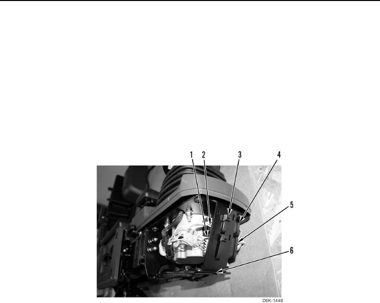
3. Connect bulldozer control connector (Figure 42, Item 2) on main harness connector (Figure 42, Item 4).
4. Connect bulldozer control connector (Figure 42, Item 1) on main harness connector (Figure 42, Item 5).
N OT E
Install tiedown straps as noted during removal.
5. Install two new tiedown straps (Figure 42, Item 3) on joystick control support assembly (Figure 42, Item 6).
Figure 42. Joystick Harness Connectors.
0238