
TM 5-2410-240-23-3
0239
REMOVAL CONTINUED
000239
N OT E
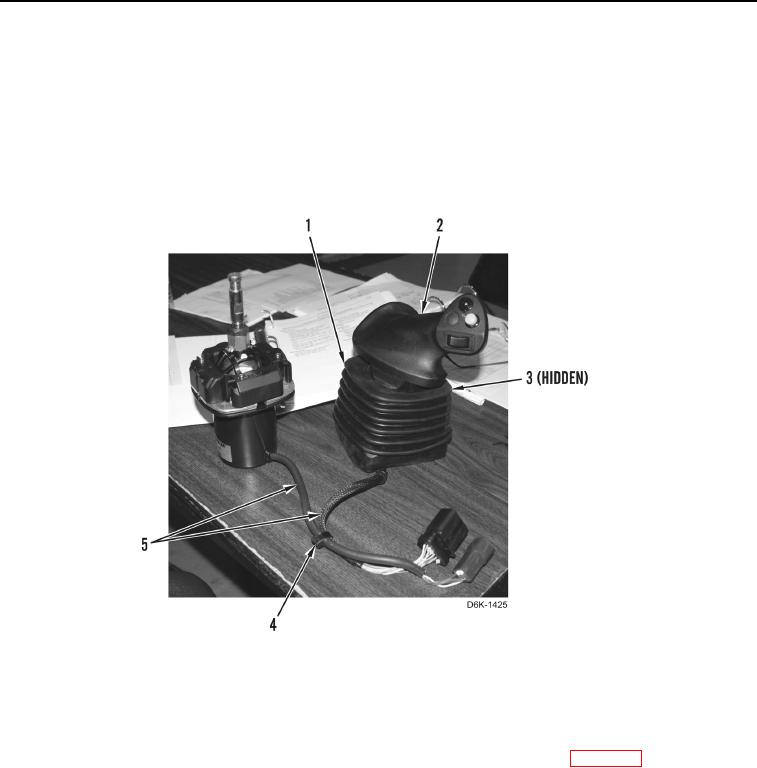
Note location of tiedown straps to aid installation.
6. Remove tiedown strap (Figure 5, Item 4) from wiring harnesses (Figure 5, Item 5). Discard tiedown strap.
7. Remove tiedown strap (Figure 5, Item 3) and boot (Figure 5, Item 1) from handle (Figure 5, Item 2). Discard
tiedown strap.
Figure 5. Joystick Handle, Boot, and Sensor.
0239
END OF TASK
CLEANING AND INSPECTION
000239
Clean and inspect all components IAW Mechanical General Maintenance Instructions (WP 0282).
END OF TASK