• Home
  • Download PDF
  • Order CD-ROM
  • Order in Print
Figure 6. Joystick Handle and Boot.
Figure 8. Joystick Harness Connectors.

Field Maintenance Manual 3 D6K Dozer Type I With Winch and Type II With Ripper
Page Navigation
  690    691    692    693    694  695  696    697    698    699    700  
img
.
TM 5-2410-240-23-3
0239
INSTALLATION CONTINUED
000239
N OT E
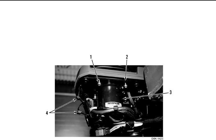
Install harness and tiedown straps as noted during removal.
5. Install joystick sensor (Figure 7, Item 3), four screws (Figure 7, Item 1), and two new tiedown straps (Figure 7,
Item 4) on support plate (Figure 7, Item 2).
Figure 7. Joystick Sensor.
0239
0239-6


Privacy Statement
Press Release
Contact

© Copyright Integrated Publishing, Inc.. All Rights Reserved.