Home
Download PDF
Order CD-ROM
Order in Print
Figure 2. Joystick Harness Connectors.
Figure 4. Joystick Handle and Boot.
Field Maintenance Manual 3 D6K Dozer Type I With Winch and Type II With Ripper
Page Navigation
695
696
697
698
699
700
701
702
703
704
705
TM
5-2410-240-23-3
0240
REMOVAL
CONTINUED
000240
6.
Remove
four
locknuts
(Figure
3,
Item
2)
and
joystick
sensor
(Figure
3,
Item
1)
from
support
plate
(Figure
3,
Item
3).
Discard locknuts.
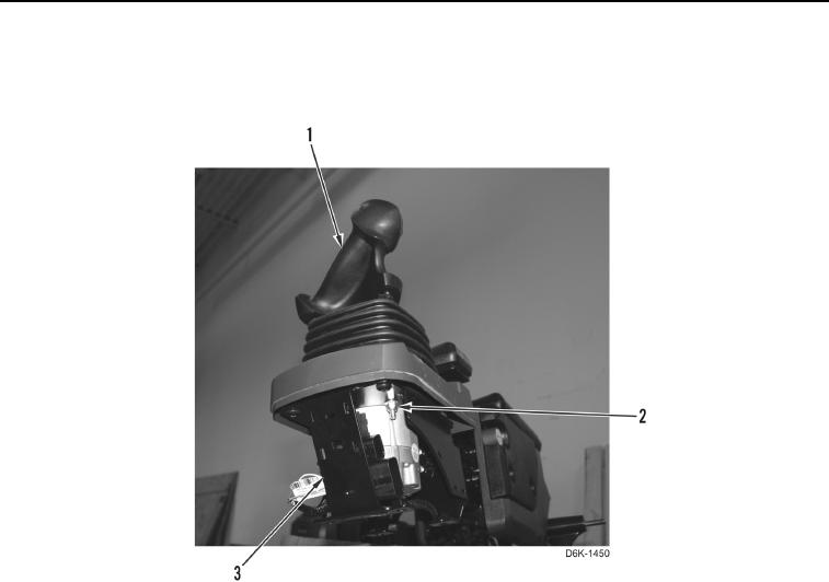
Figure 3.
Joystick
Sensor.
0240
0240-3