• Home
  • Download PDF
  • Order CD-ROM
  • Order in Print
Figure 5. Joystick Handle, Boot, and Sensor.
Figure 7. Joystick Handle and Boot.

Field Maintenance Manual 3 D6K Dozer Type I With Winch and Type II With Ripper
Page Navigation
  698    699    700    701    702  703  704    705    706    707    708  
img
.
TM 5-2410-240-23-3
0240
INSTALLATION
000240
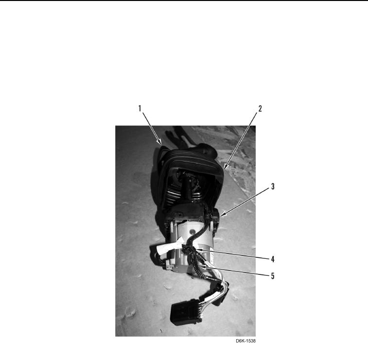
1. Install boot (Figure 6, Item 2) on handle (Figure 6, Item 1).
N OT E
Install tiedown straps as noted during removal.
2. Install wiring harness (Figure 6, Item 5) and four new tiedown straps (Figure 6, Item 4) on joystick sensor
(Figure 6, Item 3).
Figure 6. Joystick Handle, Boot, and Sensor.
0240
0240-6


Privacy Statement
Press Release
Contact

© Copyright Integrated Publishing, Inc.. All Rights Reserved.