• Home
  • Download PDF
  • Order CD-ROM
  • Order in Print
Figure 3. Joystick Sensor.
Figure 5. Joystick Handle, Boot, and Sensor.

Field Maintenance Manual 3 D6K Dozer Type I With Winch and Type II With Ripper
Page Navigation
  696    697    698    699    700  701  702    703    704    705    706  
img
.
TM 5-2410-240-23-3
0240
REMOVAL CONTINUED
000240
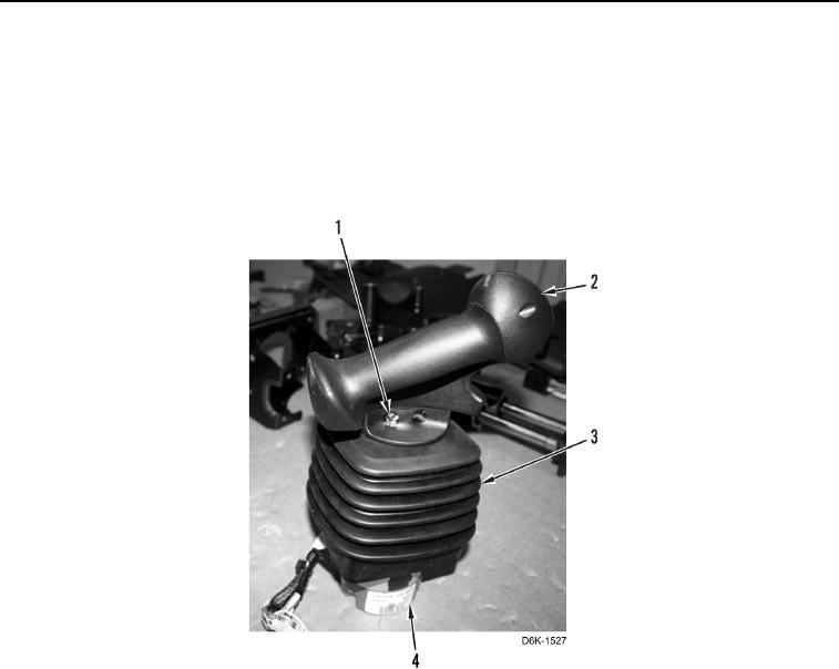
7. Remove two set screws (Figure 4, Item 1) from handle (Figure 4, Item 2).
N OT E
Note position of handle to sensor to aid installation.
8. Position handle (Figure 4, Item 2) and boot (Figure 4, Item 3) aside from joystick sensor (Figure 4, Item 4).
Figure 4. Joystick Handle and Boot.
0240
0240-4


Privacy Statement
Press Release
Contact

© Copyright Integrated Publishing, Inc.. All Rights Reserved.