
TM 5-2410-240-23-3
0239
INSTALLATION
000239
N OT E
Install tiedown strap as noted during removal.
1. Install new tiedown strap (Figure 5, Item 3) and boot (Figure 5, Item 1) on handle (Figure 5, Item 2).
2. Install new tiedown strap (Figure 5, Item 4) on wiring harnesses (Figure 5, Item 5).
WARN I N G
Use caution when using adhesives and sealants. Prolonged inhalation of vapors can
cause lung irritation. Contact with skin can cause dermatitis. Wear gloves and safety
goggles and use product in a well-ventilated area away from open flame. If ingested, keep
individual calm and seek medical attention. DO NOT induce vomiting. If contact with skin
or eyes is made, flush thoroughly with water. Dispose of cleanup rags IAW local policy and
ordinances. Failure to follow this warning may result in injury to personnel.
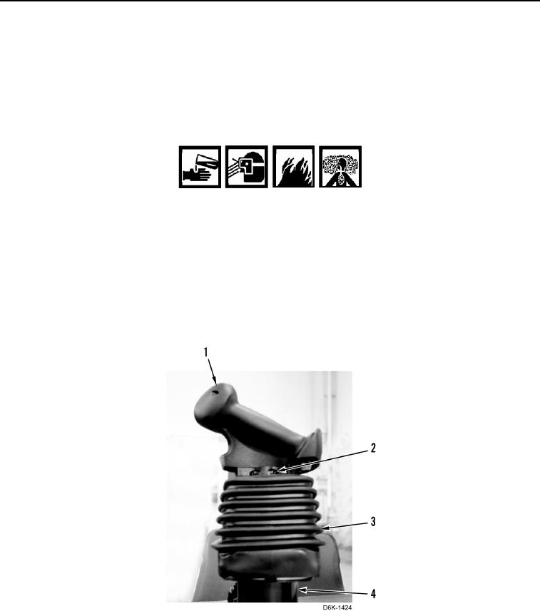
3. Apply sealing compound on two set screws (Figure 6, Item 2).
4. Install boot (Figure 6, Item 3), handle (Figure 6, Item 1), and two set screws (Figure 6, Item 2) on joystick
sensor (Figure 6, Item 4).
Figure 6. Joystick Handle and Boot.
0239