
TM 5-2410-240-23-3
0245
DISASSEMBLY CONTINUED
000245
N OT E
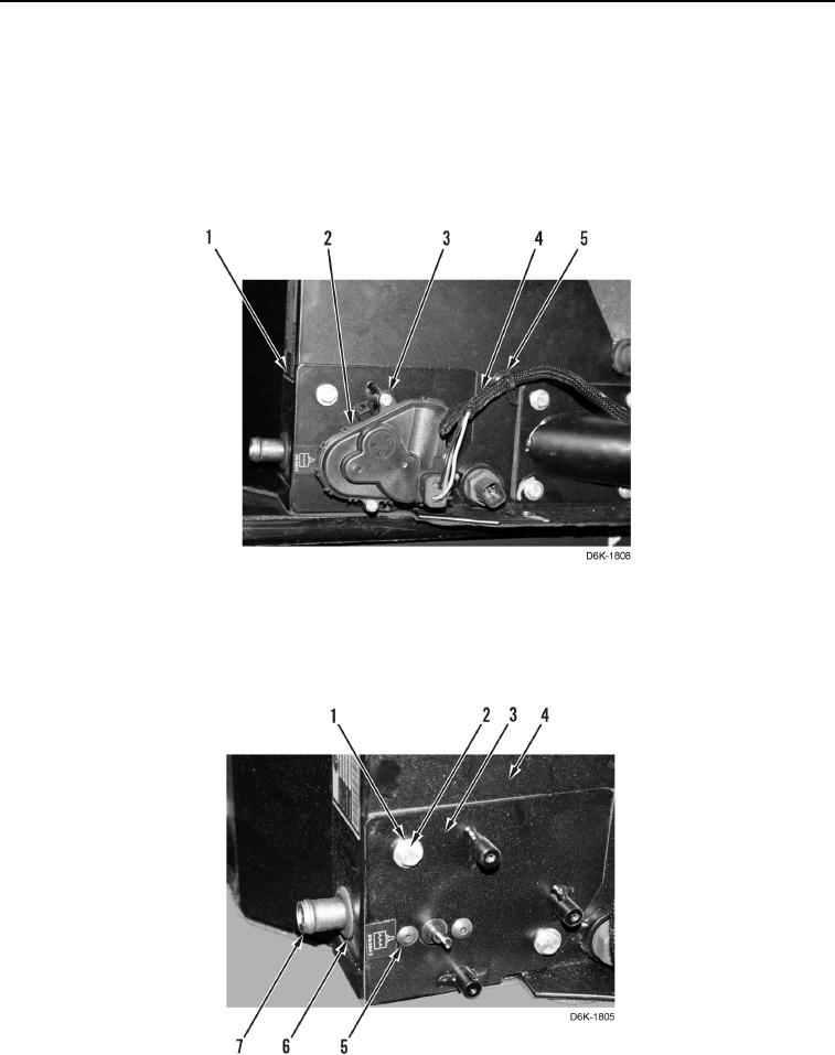
Note location of tiedown straps to aid installation.
10. Remove tiedown strap (Figure 15, Item 5) from wiring harness (Figure 15, Item 4). Discard tiedown strap and
position wiring harness aside.
11. Remove three screws (Figure 15, Item 3) and actuator (Figure 15, Item 2) from case (Figure 15, Item 1).
Figure 15. Wiring Harness, Actuator, and Retaining Hardware.
0245
12. Remove two screws (Figure 16, Item 5), bolts (Figure 16, Item 2), washers (Figure 16, Item 1), and plate
(Figure 16, Item 3) from case (Figure 16, Item 4).
13. Remove grommet (Figure 16, Item 6) from heater core (Figure 16, Item 7).
Figure 16. Grommet, Plate, and Retaining Hardware.
0245