
TM 5-2410-240-23-3
0245
DISASSEMBLY CONTINUED
000245
N OT E
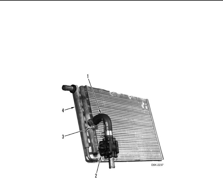
Note orientation of hose and heater valve to aid installation.
16. Loosen two clamps (Figure 18, Item 3).
17. Remove heater valve (Figure 18, Item 2) from hose (Figure 18, Item 1).
18. Remove hose (Figure 18, Item 1) from heater core (Figure 18, Item 4).
19. Remove two clamps (Figure 18, Item 3) from hose (Figure 18, Item 1).
Figure 18. Heater Valve, Hose, and Clamps.
0245