
TM 5-2410-240-23-3
0248
A/C HOSE REMOVAL CONTINUED
000248
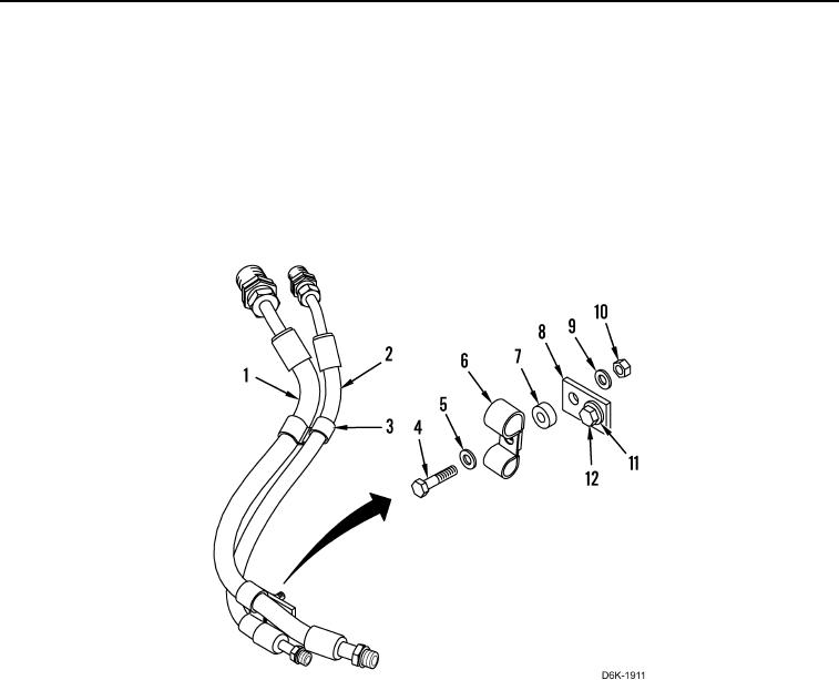
12. Remove nut (Figure 3, Item 10), washer (Figure 3, Item 9), bolt (Figure 3, Item 4), washer (Figure 3, Item 5),
two clamps (Figure 3, Item 6), and one spacer (Figure 3, Item 7) from bracket (Figure 3, Item 8).
13. Remove bolt (Figure 3, Item 12), washer (Figure 3, Item 11), and bracket (Figure 3, Item 8) from machine.
N OT E
Note location of tiedown strap to aid installation.
14. Remove tiedown strap (Figure 3, Item 3) from A/C hoses (Figure 3, Items 1 and 2). Discard tiedown strap.
Figure 3. A/C Hose Retaining Hardware Behind Right Side of Engine.
0248