
TM 5-2410-240-23-3
0248
A/C HOSE REMOVAL CONTINUED
000248
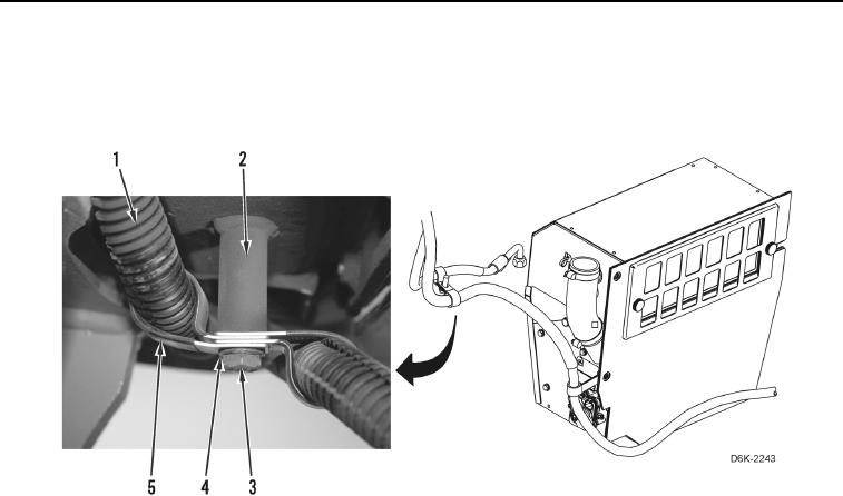
44. Remove bolt (Figure 10, Item 3), washer (Figure 10, Item 4), two clamps (Figure 10, Item 5) from machine
(Figure 10, Item 2).
45. Remove two clamps (Figure 10, Item 5) from A/C hoses (Figure 10, Item 1).
Figure 10. A/C Hose Retaining Hardware Below Right Side of A/C Heater Assembly
and Above Fuel Tank.
0248
C AU T I O N
Cap or plug all A/C hoses and fittings during removal to protect against contamination.
Failure to follow this caution may result in equipment damage.
N OT E
Tag and mark A/C hoses to aid installation.
Note orientation of fittings to aid installation.
46. Loosen two fittings (Figure 11, Item 9).
47. Remove two fittings (Figure 11, Item 9) from fittings (Figure 11, Item 7).
48. Remove two fittings (Figure 11, Item 10) from A/C hoses (Figure 11, Items 11 and 12).
49. Remove two O-rings (Figure 11, Item 14) from A/C hoses (Figure 11, Items 11 and 12). Discard O-rings.
N OT E
Note routing of A/C hoses to aid installation.
50. Remove two A/C hoses (Figure 11, Items 11 and 12) from machine (Figure 11, Item 1).
51. Remove two convoluted tubes (Figure 11, Item 13) from A/C hoses (Figure 11, Items 11 and 12).
52. Remove two nuts (Figure 11, Item 8) and fittings (Figure 11, Item 7) from bracket (Figure 11, Item 2).
53. Remove two fittings (Figure 11, Item 7) from A/C hoses (Figure 11, Items 5 and 6).
54. Remove two O-rings (Figure 11, Item 14) from A/C hoses (Figure 11, Items 5 and 6). Discard O-rings and
position A/C hoses aside.