
TM 5-2410-240-23-3
0248
A/C HOSE REMOVAL CONTINUED
000248
C AU T I O N
Cap or plug A/C hose and orifice tube during removal to protect against contamination.
Failure to follow this caution may result in equipment damage.
N OT E
Tag and mark A/C hose to aid installation.
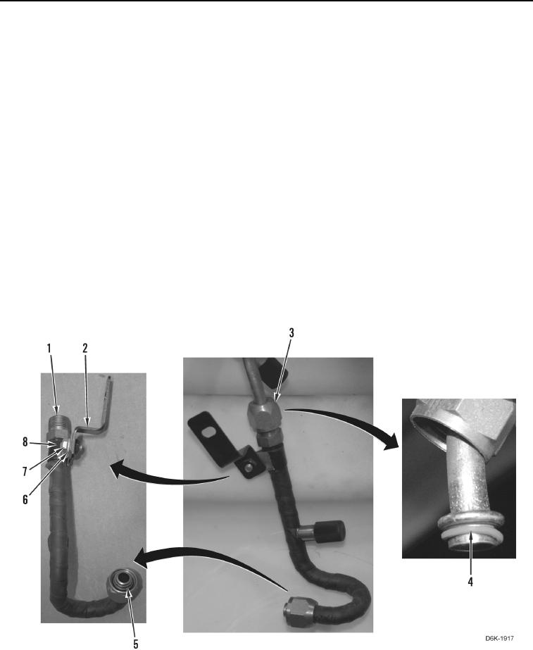
39. Disconnect orifice tube (Figure 9, Item 1) from A/C hose (Figure 9, Item 3) and position A/C hose aside.
40. Remove O-ring (Figure 9, Item 4) from A/C hose (Figure 9, Item 3). Discard O-ring and position A/C hose
aside.
41. Remove O-ring (Figure 9, Item 5) from orifice tube (Figure 9, Item 1). Discard O-ring.
N OT E
Note orientation of clamp and bracket to aid installation.
42. Remove bolt (Figure 9, Item 7), washer (Figure 9, Item 6), and bracket (Figure 9, Item 2) from clamp (Figure 9,
Item 8).
43. Remove clamp (Figure 9, Item 8) from orifice tube (Figure 9, Item 1).
Figure 9. Orifice Tube, O-ring, and Retaining Hardware.
0248