
24
TM 5-2410-241-23-1
FIELD MAINTENANCE
-
THEORY OF OPERATION: PRIMARY POWERTRAIN
000
9
PRIMARY POWERTRAIN
0009
Transfer of Mechanical Power
0009
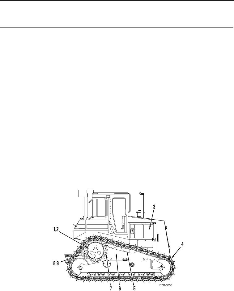
The engine (Figure 1, Item 3) is the source of the mechanical power. Power flows from engine (Figure 1, Item 3) to
tracks (Figure 1, Item 4) through the powertrain: torque divider (Figure 1, Item 5), drive shaft (Figure 1, Item 6),
power shift transmission (Figure 1, Item 8), bevel and transfer gears (Figure 1, Item 7), steering differential and
brake (Figure 1, Item 1), planetary gears and brake (Figure 1, Item 9), and final drives (Figure 1, Item 2).
The engine (Figure 1, Item 3) transfers power from the engine flywheel to the torque converter (Figure 1, Item 5).
The torque divider (Figure 1, Item 5) consists of a planetary gear arrangement and a torque converter. The torque
divider (Figure 1, Item 5) transfers power through the planetary gears and through the torque converter turbine to
the drive shaft (Figure 1, Item 6). The planetary gears are a mechanical connection and the torque converter is a
hydraulic connection.
The drive shaft (Figure 1, Item 6) transfers power to the transmission (Figure 1, Item 8). The transmission
(Figure 1, Item 8) has three speeds in the FORWARD position and three speeds in the REVERSE position.
The speed clutches and the direction clutches are electronically controlled. The clutches engage in order to
transfer power. The power output from the transmission (Figure 1, Item 8) turns the bevel and transfer gears
(Figure 1, Item 7).
The bevel and transfer gears (Figure 1, Item 7) turn the inner axle shaft, which sends power to the steering
differential and brake (Figure 1, Item 1) and the planetary gears and brake (Figure 1, Item 9).
The steering differential is used to turn the machine. The brakes are used to stop the machine. The steering
differential and brake (Figure 1, Item 1) works with the planetary gears and brake (Figure 1, Item 9) in order to send
power through the two outer axle shafts to final drives (Figure 1, Item 2). The final drives (Figure 1, Item 2) use two
planetary gear arrangements for double speed reduction. The planetary gears increase the torque in each stage.
The sprockets on the final drives transfer mechanical power to tracks (Figure 1, Item 4) that move the machine.
Figure 1. Powertrain Components.
0009