
TM 5-2410-241-23-1
0011
IMPLEMENT AND STEERING HYDRAULIC SYSTEM CONTINUED
d. Basic Valve Operation
00011
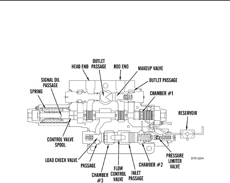
When the control valve spools are in the HOLD position, pump oil flows to the inlet passage. This passage is
common to all sections of the valve stack and this passage has no outlet. Since all the valve spools are in the
HOLD position, pump oil fills the parallel oil passages of the control valves. The pump maintains oil pressure at
525 psi (3,600 kPa). Signal oil passage, chamber #1, and resolver are drained. Head end passage, rod end
passage, and passage are blocked.
Figure 36. Ripper Tip Control Valve (HOLD).
0011