
TM 5-2410-241-23-1
0011
IMPLEMENT AND STEERING HYDRAULIC SYSTEM CONTINUED
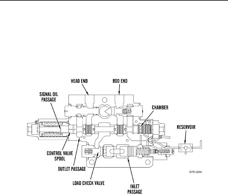
Ripper Tip Control Valve (Ripper Tip Out)
00011
When the pilot control pressure causes the valve spool to move to the TIP OUT position, cylinder oil from the rod
end passage flows through the signal oil passage to the chamber. The oil functions as signal oil. The signal oil
opens the resolver. The signal oil flows to the previous control valve and to the inlet manifold.
The increase of pump oil flow to the inlet passage opens the load check valve. The oil flows through the load check
valve. The oil then flows around the valve spool and out the rod end passage to the rod end of the ripper tip
cylinders. The ripper tip cylinders tip the ripper outward.
Return oil from the head end of the ripper tip cylinders flows through the head end passage, around the valve
spool, and through the outlet passage to the tank.
Figure 38. Ripper Tip Control Valve (RIPPER TIP OUT).
0011