TM 5-2410-241-23-1
0011
IMPLEMENT AND STEERING HYDRAULIC SYSTEM CONTINUED
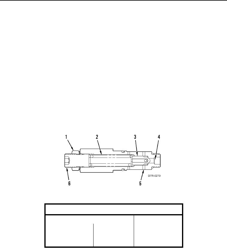
The main relief valve is a directly operated valve. Since the setting of the main relief valve is above all of the
operating pressures, the valve serves as a backup valve. The main relief valve limits the increases (spikes) in
pump pressure.
N OT E
The main relief valve is not capable of handling full pump flow.
Pump oil flows through the inlet passage (Figure 42, Item 4) to the valve (Figure 42, Item 3). A spring (Figure 42,
Item 2) keeps the valve (Figure 42, Item 3) closed when the oil pressure is less than the setting of the relief valve.
When the oil pressure increases to the setting of the relief valve, the valve (Figure 42, Item 3) opens. The oil in
passage (Figure 42, Item 4) flows around the valve (Figure 42, Item 3). The oil flows through drain passages
(Figure 42, Item 5) to the tank. The pump pressure can not exceed the setting of the main relief valve.
The compressed length of spring (Figure 42, Item 2) determines the force that is applied by the spring (Figure 42,
Item 2) to the valve (Figure 42, Item 3). An increase or a decrease in the force that is applied by the spring
(Figure 42, Item 2) changes the pressure setting of the relief valve.
Loosen nut (Figure 42, Item 1) and turn setscrew (Figure 42, Item 6) clockwise in order to increase the pressure
setting. Loosen nut (Figure 42, Item 1) and turn setscrew (Figure 42, Item 6) counterclockwise in order to decrease
the pressure setting. The pressure setting is specified in the following table. The test was completed at a
temperature of 120F 5F (49C 3C).
Figure 42. Main Relief Valve.
0011
Pressure and Flow
Pressure
Flow
Inlet
Outlet
Inlet
42,000 400 kPa
70 7 kPa
5 1 L/min (1.3
(6,090 60 psi)
(10 1 psi)
0.3 US gal.min)

