• Home
  • Download PDF
  • Order CD-ROM
  • Order in Print
Figure 40. Winch Control Valve (REEL OUT).
Figure 42. Main Relief Valve.

Field Maintenance Manual 1 D7R Dozer Type I With Winch and Type II With Ripper
Page Navigation
  153    154    155    156    157  158  159    160    161    162    163  
img
.
TM 5-2410-241-23-1
0011
IMPLEMENT AND STEERING HYDRAULIC SYSTEM CONTINUED
Relief Valve (Main)
00011
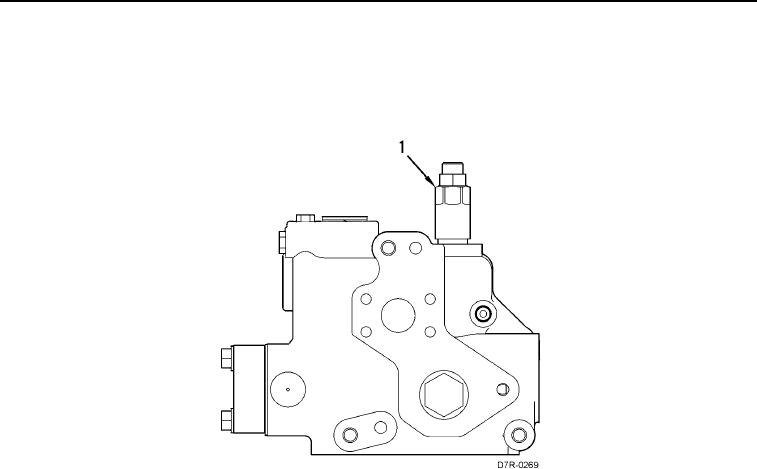
The main relief valve (Figure 41, Item 1) is located in the inlet manifold. The inlet manifold is attached to the bottom
of the control valve stack.
Figure 41. Main Relief Valve in Inlet Manifold.
0011
0011-49


Privacy Statement
Press Release
Contact

© Copyright Integrated Publishing, Inc.. All Rights Reserved.