
TM 5-2410-241-23-1
0019
Table 2. Engine Troubleshooting Procedures - Continued.
MALFUNCTION
TEST OR INSPECTION
CORRECTIVE ACTION
1-11 Cylinder #1 Injector
8. Disconnect engine ECM connec-
Fault - Continued
tor N-C1 (WP 0018, Figure 2)
from engine ECM (WP 0101).
9. Using digital multimeter
1. If continuity is found, replace
(WP 0296), test for continuity
engine ECM (WP 0101). Remove
between pins 38 and 44 on
jumper wire from pins 1 and 12 on
engine ECM connector N-C1
engine harness connector N-C2
(WP 0018, Figure 2).
(WP 0018, Figure 7) and connect
engine harness connector N-C2
(WP 0018 Figure 7) on valve
cover side connector NN-C1
(WP 0018, Figure 8).
2. If continuity is not found, replace
engine main wiring harness
(WP 0055). Ensure all harness
connectors are reconnected. Ver-
ify correct operation of machine
(TM 5-2410-241-10).
10. Remove jumper wire from pins 1
and 12 on engine harness con-
nector N-C2 (WP 0018, Figure 7)
and connect engine harness con-
nector N-C2 (WP 0018, Figure 7)
on valve cover side connector
NN-C1 (WP 0018, Figure 8).
11. Remove valve cover (WP 0106).
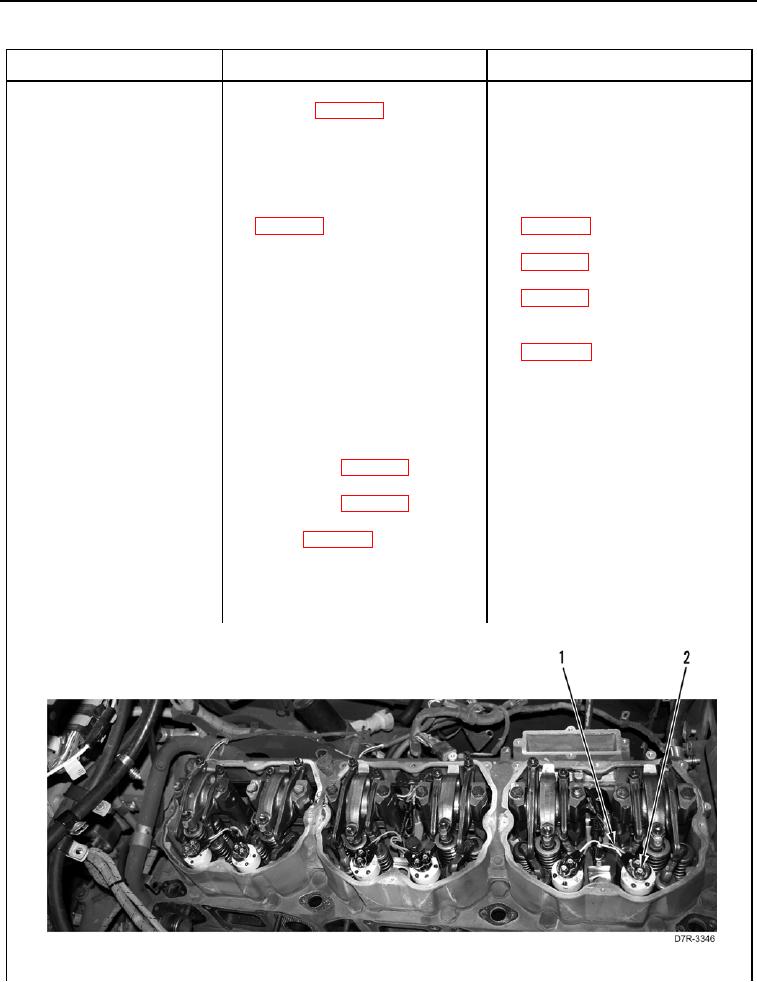
12. Install jumper wire between nuts
(Figure 2, Item 2).
Figure 2. Cylinder #1 Injector Fault Code.
019