
TM 5-2410-241-23-1
0019
Table 2. Engine Troubleshooting Procedures - Continued.
MALFUNCTION
TEST OR INSPECTION
CORRECTIVE ACTION
168-2 System Voltage Inter-
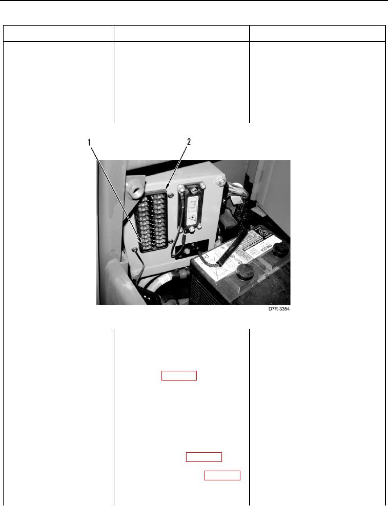
5. Remove fuse #21 (Figure 11,
mittent/Erratic -
Item 1) located in the fuse panel
Continued
(Figure 11, Item 2).
6. Using digital multimeter
1. If Fuse #21 is OK, verify correct
(WP 0296), test for continuity
operation of machine (TM 5-2410-
between blades on fuse.
241-10).
2. If problem is found, proceed to
step 7.
Figure 11. Fuse #21.
019
7. Turn ignition switch and battery
disconnect switch to OFF position
(TM 5-2410-241-10).
8. Disconnect engine ECM connec-
tor V-C4 (WP 0018, Figure 1)
from engine ECM.
9. Turn battery disconnect switch
and ignition switch to ON position
(TM 5-2410-241-10).
10. Using digital multimeter
1.
If voltage is found, proceed to
(WP 0296), measure for voltage
step 11.
between pin 48 on ECM harness 2.
If voltage is not found, proceed to
connector V-C4 (WP 0018,
step 14.
Figure 1) and 61 pin on ECM har-
ness connector V-C4 (WP 0018,
Figure 1).
0019-46