
TM 5-2410-241-23-1
0019
Table 2. Engine Troubleshooting Procedures - Continued.
MALFUNCTION
TEST OR INSPECTION
CORRECTIVE ACTION
168-2 System Voltage Inter-
24. Using digital multimeter
1. If continuity is found, proceed to
mittent/Erratic -
(WP 0296), test for continuity
step 25.
Continued
between pin 65 on ECM harness
2. If continuity is not found, replace
connector V-C4 (WP 0018,
ECM harness (WP 0105). Ensure
Figure 1) and ground.
all harness connectors are recon-
nected. Verify correct operation of
machine (TM 5-2410-241-10).
25. Disconnect ECM harness connec-
tor MA-C3 (WP 0018, Figure 21)
from fuse panel harness connec-
tor A-C1 (WP 0018, Figure 22).
26. Using digital multimeter
1. If continuity is found, proceed to
(WP 0296), test for continuity
step 27.
between pin 11 on ECM harness
2. If continuity is not found, replace
connector MA-C3 (WP 0018, Fig-
platform harness (WP 0209).
ure 21) and pin 2 on ECM har-
Ensure all harness connectors
ness connector MA-C22 (WP
are reconnected. Verify correct
0018, Figure 11).
operation of machine (TM 5-2410-
241-10).
27. Using digital multimeter
1. If continuity is found, proceed to
(WP 0296), test for continuity
step 28.
between pin 12 on ECM harness
2. If continuity is not found, replace
connector MA-C3 (WP 0018,
platform harness (WP 0209).
Figure 21) and pin 11 on ECM
Ensure all harness connectors
harness connector MA-C22
are reconnected. Verify correct
(WP 0018, Figure 11).
operation of machine (TM 5-2410-
241-10).
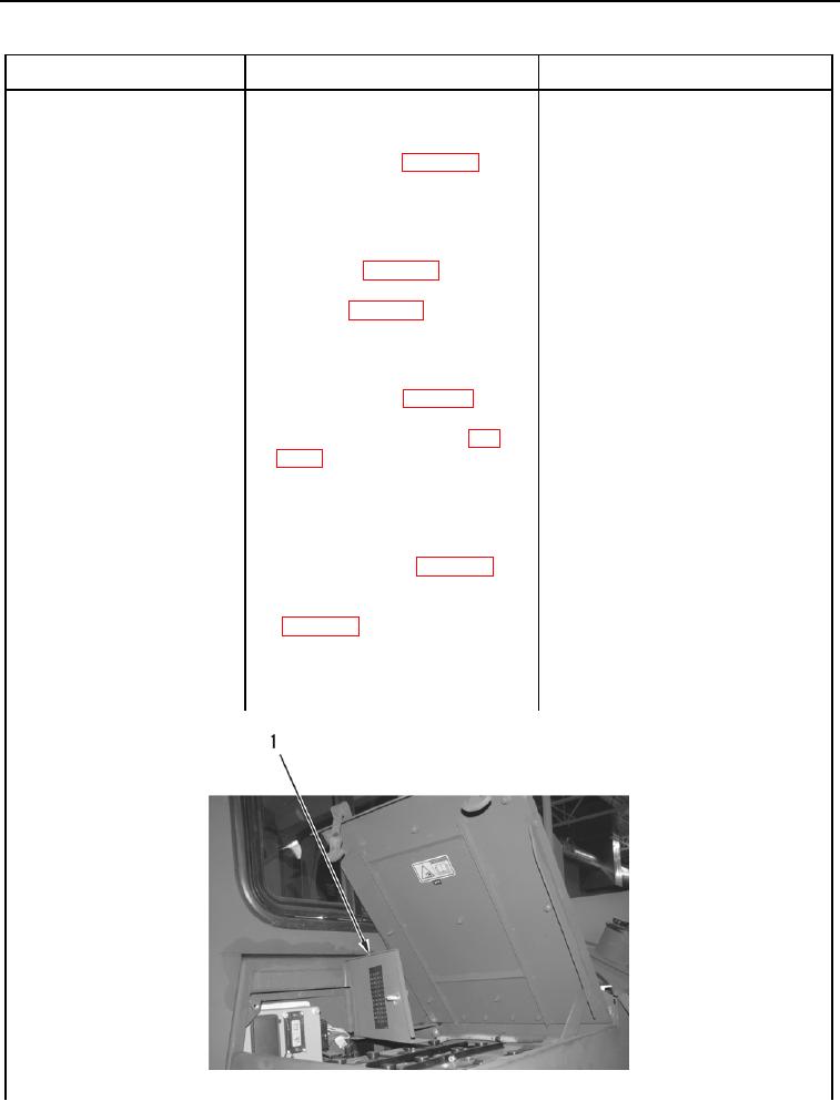
28. Open fuse panel door
(Figure 12, Item 1).
Figure 12. Fuse Panel Door.
019