
TM 5-2410-241-23-1
0019
Table 2. Engine Troubleshooting Procedures - Continued.
MALFUNCTION
TEST OR INSPECTION
CORRECTIVE ACTION
168-2 System Voltage Inter-
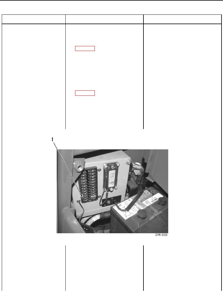
29. Using digital multimeter
1.
If continuity is found, proceed to
mittent/Erratic -
(WP 0296), test for continuity
step 30.
Continued
between pin 11 on fuse panel wir- 2.
If continuity is not found, replace
ing harness connector A-C1
fuse panel wiring harness
(WP 0018, Figure 22) and left
(WP 0176). Ensure all harness
cavity of ECM Fuse #21
connectors are reconnected. Ver-
(Figure 13, Item 1).
ify correct operation of machine
(TM 5-2410-241-10).
30. Using digital multimeter
1.
If continuity is found, replace
(WP 0296), test for continuity
engine ECM (WP 0101). Ensure
between pin 12 on fuse panel wir-
all harness connectors are recon-
ing harness connector A-C1
nected. Verify correct operation of
(WP 0018, Figure 22) and left
machine (TM 5-2410-241-10).
cavity of ECM Fuse #21
2.
If continuity is not found, replace
(Figure 13, Item 1).
fuse panel wiring harness
(WP 0176). Ensure all harness
connectors are reconnected.
Verify correct operation of
machine (TM 5-2410-241-10).
Figure 13. Fuse #21.
019