
TM 5-2410-241-23-1
0020
Table 1. Powertrain Troubleshooting Procedures - Continued.
0020
MALFUNCTION
TEST OR INSPECTION
CORRECTIVE ACTION
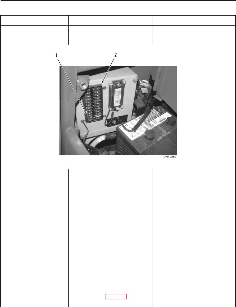
168-4 Electrical System Volt- 6. Remove ECM Fuse #19 (Figure 2,
age Below Normal - Con-
Item 1) from fuse panel (Figure 2,
tinued
Item 2 (TM 5-2410-241-10).
Figure 2. ECM Fuse #19.
0020
7. Using a digital multimeter (WP
1. If continuity is NOT found, replace
0296), test for continuity between
ECM Fuse #19, and proceed to
blades of ECM Fuse #19.
step 8.
2. If continuity is found, install ECM
Fuse #19 on fuse panel, and pro-
ceed to step 10.
1. If ECM Fuse #19 is blown, pro-
8. Turn ignition switch and battery
ceed to step 31.
disconnect switch to ON position
(TM 5-2410-241-10).
2. If code 168-4 returns, proceed to
step 9.
3. If ECM Fuse #19 is OK and code
168-4 does not return, verify cor-
rect operation of machine (TM 5-
2410-241-10).
9. Turn ignition switch and battery
disconnect switch to OFF position
(TM 5-2410-241-10).
10. Remove left platform access panel
(WP 0207).
11. Disconnect powertrain ECM con-
nector X-C2 (WP 0018, Figure 4)
from powertrain ECM.