
TM 5-2410-241-23-1
0020
Table 1. Powertrain Troubleshooting Procedures - Continued.
0020
MALFUNCTION
TEST OR INSPECTION
CORRECTIVE ACTION
168-4 Electrical System Volt- 30. Using a digital multimeter (WP
1. If continuity is found, replace pow-
age Below Normal - Con-
0296), test for continuity between
ertrain ECM (WP 0175). Ensure all
tinued
pin 22 on fuse panel wiring har-
harness connectors are recon-
ness connector A-C1 (WP 0018,
nected. Verify correct operation of
Figure 22) and left cavity of ECM
machine (TM 5-2410-241-10).
Fuse #19.
2. If continuity is NOT found, replace
fuse panel wiring harness (WP
0176). Install ECM Fuse #19 on
fuse panel. Ensure all harness
connectors are reconnected. Ver-
ify correct operation of machine
(TM 5-2410-241-10).
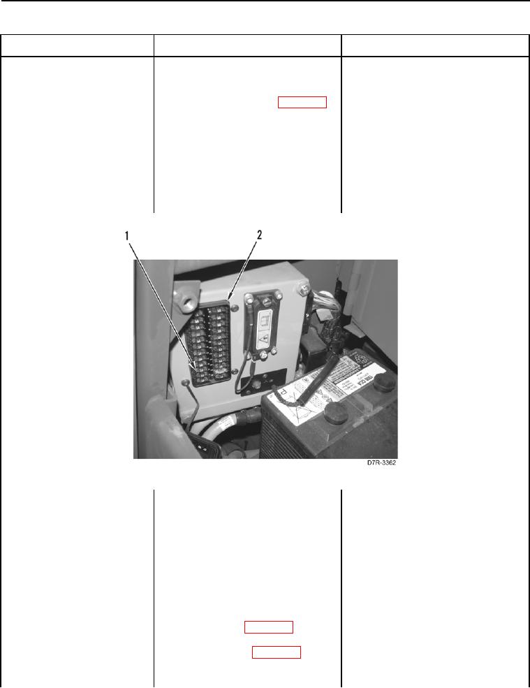
Figure 3. ECM Fuse #19.
0020
31. Turn ignition switch and battery
disconnect switch to OFF position
(TM 5-2410-241-10).
32. Remove ECM Fuse #19 (Figure 3,
Item 1) from fuse panel (Figure 3,
Item 2). (TM 5-2410-241-10).
33. Remove left platform access panel
(WP 0207).
34. Disconnect platform harness con-
nector MA-C3 (WP 0018, Figure
21) from fuse panel wiring harness
connector A-C1 (WP 0018, Figure
22).