
TM 5-2410-241-23-1
0020
Table 1. Powertrain Troubleshooting Procedures - Continued.
0020
MALFUNCTION
TEST OR INSPECTION
CORRECTIVE ACTION
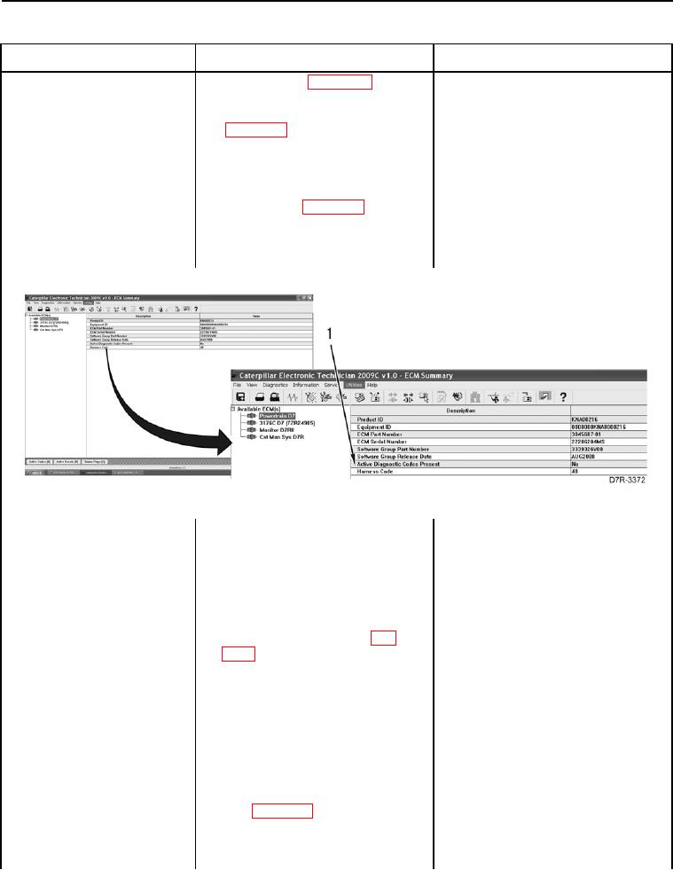
368-2 Autoshift Switch Data
1. Connect MSD (WP 0016), select
1. If active 368-2 code is present,
Erratic, Intermittent, or
Powertrain D7 ECM, and check for
proceed to step 4.
Incorrect
Diagnostic Codes or Event Codes
2. If active 368-2 code is NOT pres-
ent, proceed to step 2.
2. Activate Auto Shift Switch (TM 5-
2410-241-10).
3. Check for Diagnostic Codes or
1. If active 368-2 code is present,
Event Codes (WP 0013) (Figure
proceed to step 4.
18, Item 1).
2. If no active code is present, the
problem does NOT exist at this
time. Resume normal operation.
Figure 18. Diagnostic Codes.
0020
4. Turn ignition switch and battery
disconnect switch to OFF position
(TM 5-2410-241-10).
5. Remove left platform access panel
(WP 0207).
6. Disconnect bi-directional mode
switch connector E-C11 (WP
0018, Figure 50) from auto shift
switch.
7. Turn ignition switch and battery
disconnect switch to ON position
(TM 5-2410-241-10).
8. Using a digital multimeter (WP
1. If voltage of 12.5 to 13.5 volts is
0296), measure for voltage
found, proceed to step 9.
between pins A and C on bi-direc-
2. If voltage of 12.5 to 13.5 volts is
tional mode switch connector E-
NOT found, proceed to step 10.
C11 (WP 0018, Figure 50).