
TM 5-2410-241-23-1
0051
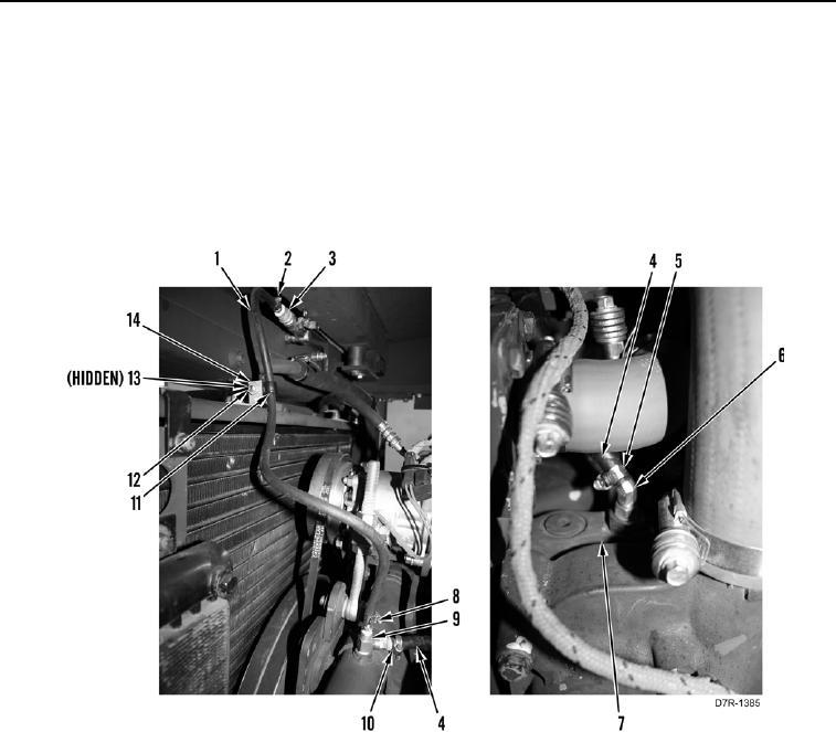
VENT LINE REMOVAL
00051
1. Remove clamp (Figure 10, Item 2) and hose (Figure 10, Item 1) from valve (Figure 10, Item 3).
2. Remove bolt (Figure 10, Item 12), washer (Figure 10, Item 13), clip (Figure 10, Item 11) and hose (Figure 10,
Item 1) from bracket (Figure 10, Item 14).
3. Remove clamp (Figure 10, Item 8) and hose (Figure 10, Item 1) from fitting (Figure 10, Item 9).
4. Remove clamp (Figure 10, Item 10) and hose (Figure 10, Item 4) from fitting (Figure 10, Item 9).
5. Remove clamp (Figure 10, Item 5) and hose (Figure 10, Item 4) from fitting (Figure 10, Item 6) on water
temperature regulator (Figure 10, Item 7).
Figure 10. Vent Lines.
0051
END OF TASK
CLEANING AND INSPECTION
00051
Clean and inspect all parts IAW Mechanical General Maintenance Instructions (WP 0295).
END OF TASK