
TM 5-2410-241-23-2
0057
ENGINE REMOVAL CONTINUED
N OT E
Tag and mark all lines, hoses and electrical connections to aid installation.
Note location and quantity of tiedown straps to aid installation.
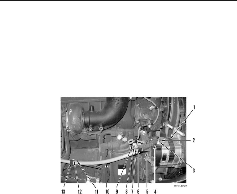
44. Remove two locknuts (Figure 14, Item 12), washers (Figure 14, Item 11) and clamps (Figure 14, Item 13) from
alternator cable (Figure 14, Item 10). Discard locknuts.
45. Remove bolt (Figure 14, Item 7), washer (Figure 14, Item 8), clamp (Figure 14, Item 9) and bracket (Figure 14,
Item 6) from alternator bracket (Figure 14, Item 5).
46. Position boot (Figure 14, Item 4) aside.
47. Remove nut (Figure 14, Item 2), two washers (Figure 14, Item 3) and alternator cable (Figure 14, Item 10) from
alternator (Figure 14, Item 1). Set cable aside.
Figure 14. Alternator Cable.
0057