
TM 5-2410-241-23-2
0057
REMOVE ENGINE FROM STAND CONTINUED
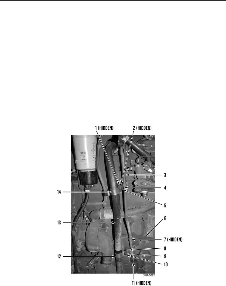
7. Position fuel hose (Figure 35, Item 6) and tighten bolt (Figure 35, Item 7) on engine.
8. Install new O-ring (Figure 35, Item 11) on oil dipstick tube (Figure 35, Item 3).
9. Install oil dipstick tube (Figure 35, Item 3), washer (Figure 35, Item 2) and bolt (Figure 35, Item 1) on engine.
N OT E
Install spacer and oil dipstick mounting bracket as noted during removal.
10. Position hose (Figure 35, Item 13) and P-clip (Figure 35, Item 12) on engine.
11. Install spacer (Figure 35, Item 8), P-clip (Figure 35, Item 12), washer (Figure 35, Item 9), and bolt (Figure 35,
Item 10) on engine.
N OT E
Install oil dipstick mounting bracket as noted during removal.
12. Position P-clip (Figure 35, Item 14) on engine.
13. Install washer (Figure 35, Item 5) and bolt (Figure 35, Item 4) on engine.
Figure 35. Oil Dipstick Tube.
0057