
TM 5-2410-241-23-2
0057
REMOVE ENGINE FROM STAND CONTINUED
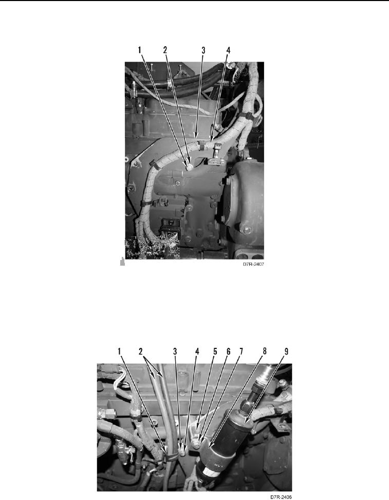
26. Position harness (Figure 41, Item 4) and install bracket (Figure 41, Item 3), washer (Figure 41, Item 2) and bolt
(Figure 41, Item 1).
Figure 41. Harness and Bracket.
0057
27. Position NATO slave cables (Figure 42, Item 2) and install clamp (Figure 42, Item 1), washer (Figure 42, Item
3) and bolt (Figure 42, Item 4).
28. Install clamp (Figure 42, Item 8), receiver dryer (Figure 42, Item 9), spacer (Figure 42, Item 5), washer
(Figure 42, Item 6) and bolt (Figure 42, Item 7) on engine.
Figure 42. Receiver/Dryer.
0057