
TM 5-2410-241-23-2
0068
REMOVAL CONTINUED
N OT E
Note position of bolts and clips to aid installation.
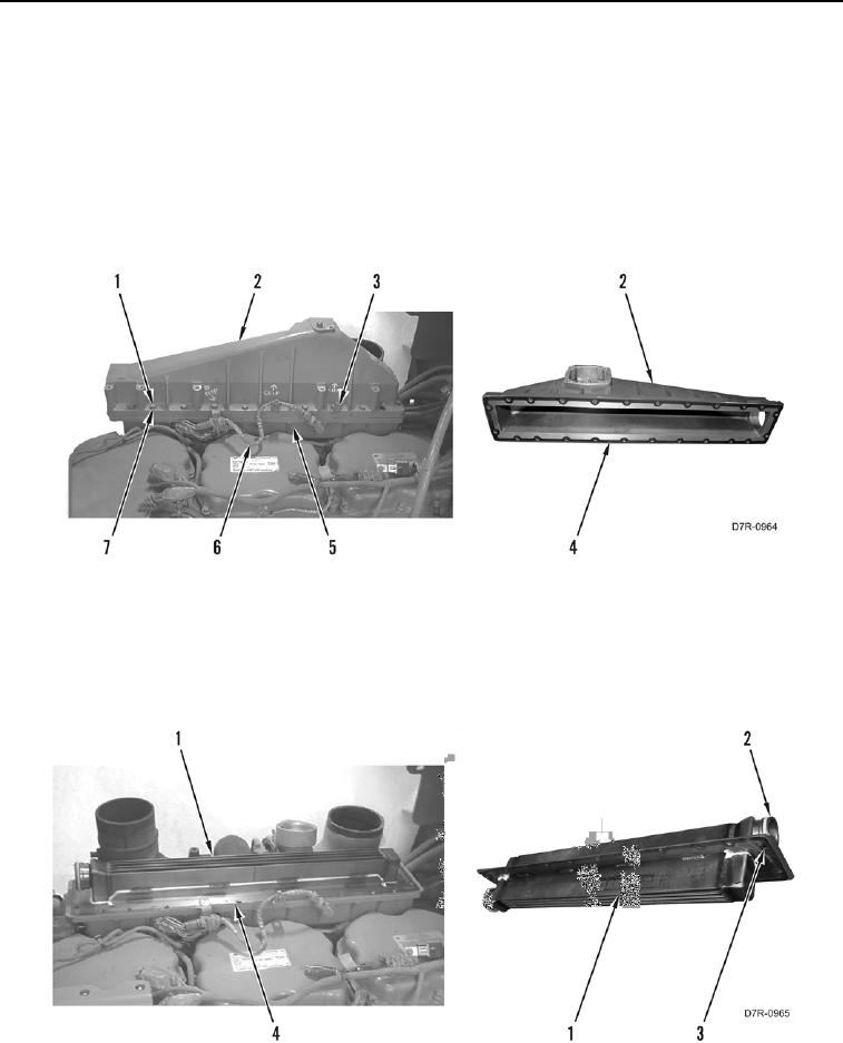
10. Remove 24 bolts (Figure 6, Item 1), 22 washers (Figure 6, Item 7), two clips (Figure 6, Item 3), wiring harness
(Figure 6, Item 6) and aftercooler housing cover (Figure 6, Item 2) from aftercooler lower housing (Figure 6,
Item 5). Set harness aside.
11. Remove gasket (Figure 6, Item 4) from aftercooler housing cover (Figure 6, Item 2). Discard gasket.
Figure 6. Aftercooler Housing Upper Cover.
0068
12. Remove aftercooler core (Figure 7, Item 1) from aftercooler lower housing (Figure 7, Item 4).
13. Remove two O-rings (Figure 7, Item 2) and gasket (Figure 7, Item 3) from aftercooler core (Figure 7, Item 1).
Discard O-rings and gasket.
Figure 7. Aftercooler Core.
0068