
TM 5-2410-241-23-2
0069
REMOVAL CONTINUED
N OT E
Mark location and orientation of valve bridges for installation.
Tag and mark electrical connectors to aid with installation.
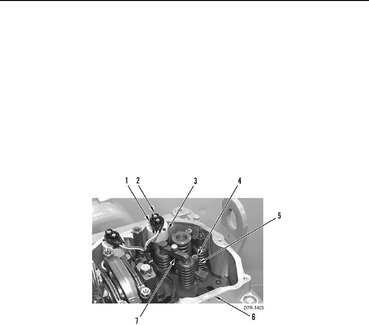
2. Remove valve bridge assemblies (Figure 2, Item 7) from cylinder head (Figure 2, Item 6).
3. Loosen nuts (Figure 2, Item 2) and disconnect harness connector (Figure 2, Item 1) from fuel injector (Figure 2,
Item 3).
N OT E
Mark injector location for installation.
4. Remove fuel injector hold-down bolt (Figure 2, Item 4) and spacer (Figure 2, Item 5). Discard hold-down bolt.
5. Pry fuel injector (Figure 2, Item 3) out of cylinder head assembly (Figure 2, Item 6).
Figure 2. Fuel Injection Manifold.
0069