• Home
  • Download PDF
  • Order CD-ROM
  • Order in Print
Figure 4. Fuel Injection Manifold.
Figure 6. Fuel Injection Manifold.

Field Maintenance Manual D7R Dozer Type I With Winch and Type II With Ripper
Page Navigation
  195    196    197    198    199  200  201    202    203    204    205  
img
.
TM 5-2410-241-23-2
0069
INSTALLATION CONTINUED
N OT E
Install clamp as noted during removal.
Clamp is stamped "THIS SIDE UP."
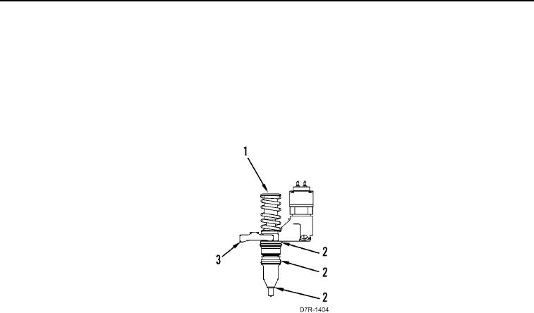
2. Install clamp (Figure 5, Item 3) and three new O-ring seals (Figure 5, Item 2) on each fuel injector (Figure 5,
Item 1).
Figure 5. Fuel Injection Manifold.
0069
0069-5


Privacy Statement
Press Release
Contact

© Copyright Integrated Publishing, Inc.. All Rights Reserved.