
TM 5-2410-241-23-2
0069
INSTALLATION CONTINUED
N OT E
Install fuel injectors as marked during removal.
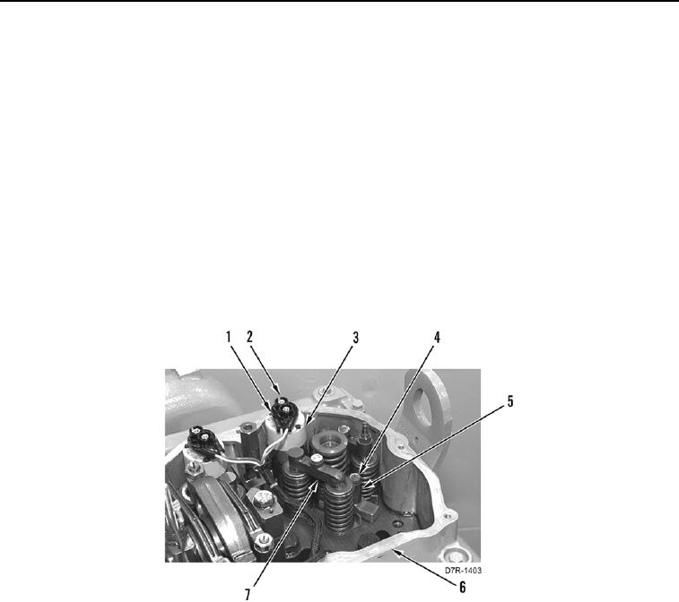
3. Install fuel injector (Figure 6, Item 3) on cylinder head assembly (Figure 6, Item 6).
4. Install spacer (Figure 6, Item 5) and new fuel injector hold down bolt (Figure 6, Item 4) on cylinder head
(Figure 6, Item 6). Tighten fuel injector hold down bolt to 22 lb-ft (30 Nm).
5. Connect harness connector (Figure 6, Item 1) to fuel injector (Figure 6, Item 3) and tighten nuts (Figure 6,
Item 2).
N OT E
Install valve bridges as marked during removal.
Tag and mark electrical connectors to aid with installation.
6. Install valve bridge assemblies (Figure 6, Item 7) on cylinder head (Figure 6, Item 6).
Figure 6. Fuel Injection Manifold.
0069