
TM 5-2410-241-23-2
0077
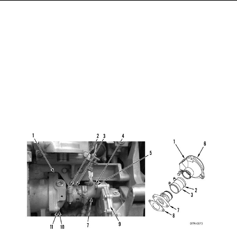
INSTALLATION CONTINUED
N OT E
Install hoses as tagged during removal.
6. Install two clamps (Figure 7, Item 2) on hose (Figure 7, Item 3).
7. Install hose (Figure 7, Item 3) on water pump elbow (Figure 7, Item 7) and oil cooler housing cap (Figure 7,
Item 1).
8. Install new gasket (Figure 7, Item 8) on water pump elbow (Figure 7, Item 7).
9. Install new O-ring (Figure 7, Item 6) on oil cooler housing cap (Figure 7, Item 1).
10. Install oil cooler housing cap (Figure 7, Item 1), water pump elbow (Figure 7, Item 7) and hose (Figure 7,
Item 3) on machine.
11. Install three washers (Figure 7, Item 11) and bolts (Figure 7, Item 10) on oil cooler housing cap (Figure 7,
Item 1).
12. Install two washers (Figure 7, Item 5) and bolts (Figure 7, Item 4) on water pump elbow (Figure 7, Item 7) on
water pump (Figure 7, Item 9).
13. Tighten two clamps (Figure 7, Item 2) on hose (Figure 7, Item 3).
Figure 7. Oil Cooler Connection.
0077
END OF TASK