
TM 5-2410-241-23-2
0097
REMOVAL
00097
N OT E
Tag and mark electrical connectors to aid installation.
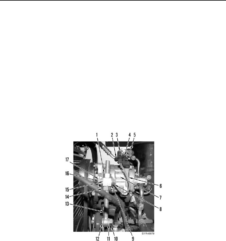
1. Remove tiedown strap (Figure 1, Item 4) and disconnect connector (Figure 1, Item 3) from connector (Figure 1,
Item 2). Discard tiedown strap.
2. Position harness (Figure 1, Item 5) and harness (Figure 1, Item 6) aside.
N OT E
Note proper belt tension before loosening nuts.
3. Loosen nut (Figure 1, Item 1) and nut (Figure 1, Item 14) from block (Figure 1, Item 15).
4. Remove nut (Figure 1, Item 8), washer (Figure 1, Item 9), bolts (Figure 1, Item 16) and washer (Figure 1,
Item 17) from block (Figure 1, Item 15).
5. Remove bolt (Figure 1, Item 10), washer (Figure 1, Item 11), shaft (Figure 1, Item 13) and washer (Figure 1,
Item 12) from A/C compressor (Figure 1, Item 7).
6. Remove nut (Figure 1, Item 1), block (Figure 1, Item 15), and nut (Figure 1, Item 14) from shaft (Figure 1,
Item 13).
Figure 1. Compressor Adjusting Shaft.
0097