
TM 5-2410-241-23-2
0099
REMOVAL
00099
N OT E
Tag and mark wiring harnesses to aid installation.
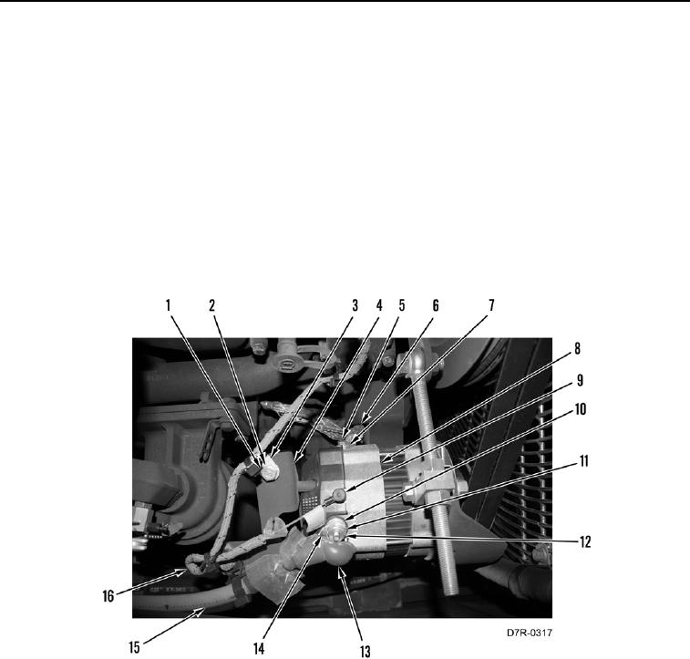
1. Position boot (Figure 1, Item 13) aside.
2. Remove nut (Figure 1, Item 12), lockwasher (Figure 1, Item 10), washer (Figure 1, Item 11), and harness
connector (Figure 1, Item 14) from alternator (Figure 1, Item 8). Discard lockwasher.
3. Disconnect wire (Figure 1, Item 9) from alternator (Figure 1, Item 8).
4. Remove bolt (Figure 1, Item 5), two washers (Figure 1, Item 7), and ground strap (Figure 1, Item 6) from
alternator (Figure 1, Item 8). Position ground strap aside.
5. Remove two bolts (Figure 1, Item 1), washers (Figure 1, Item 2), and three clips (Figure 1, Item 3) from bracket
(Figure 1, Item 4). Position wiring harnesses (Figure 1, Items 15 and 16) aside.
Figure 1. Alternator, Wiring, and Retaining Hardware.
099