
TM 5-2410-241-23-2
0119
REMOVAL CONTINUED
N OT E
Note size and position of O-rings to aid installation.
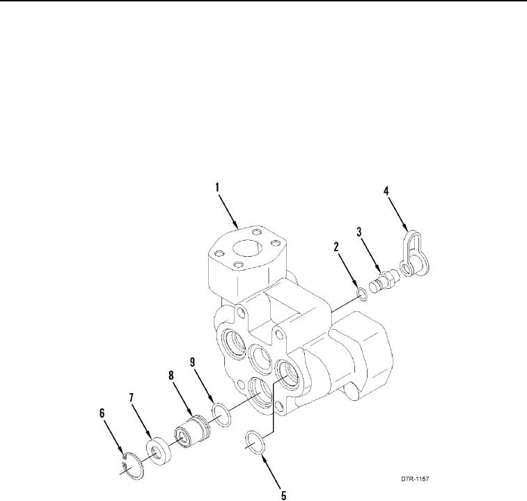
7. Remove three O-rings (Figure 2, Item 5) from manifold (Figure 2, Item 1). Discard O-rings.
8. Remove cap (Figure 2, Item 4), fitting (Figure 2, Item 3), and O-ring (Figure 2, Item 2) from manifold (Figure 2,
Item 1). Discard O-ring.
9. Remove retaining ring (Figure 2, Item 6), retainer (Figure 2, Item 7), valve (Figure 2, Item 8), and O-ring
(Figure 2, Item 9) from manifold (Figure 2, Item 1). Discard O-ring.
Figure 2. Valve.
0119
END OF TASK
CLEANING AND INSPECTION
000119
Clean and inspect all parts IAW Mechanical General Maintenance Instructions (WP 0295).
END OF TASK