
TM 5-2410-241-23-2
0118
FLANGE TYPE HOSE INSTALLATION
000118
N OT E
Hydraulic hoses, fittings, and clamps are al installed in generally the same method. This
l
procedure covers installation of one hydraulic hose assembly on machine.
This procedure will install one hose with flan e at each end. Follow the same procedure
g
for additional hoses with flange at each end.
Install lines and hoses as noted during removal.
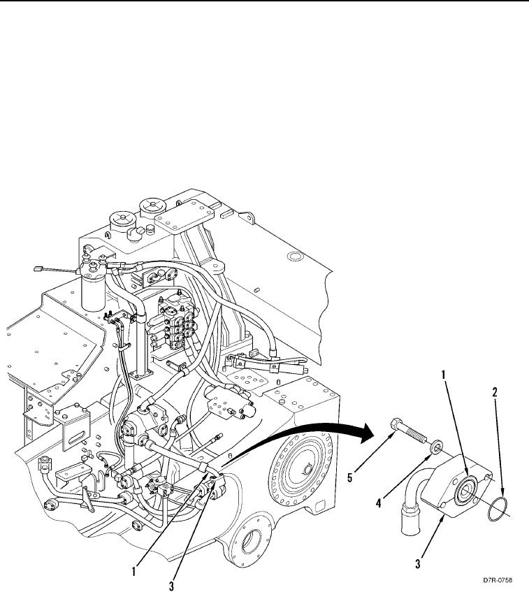
1. Install two O-rings (Figure 6, Item 2) and four flanges (Figure 6, Item 3) on hose (Figure 6, Item 1).
2. Install hose (Figure 6, Item 1), eight washers (Figure 6, Item 4), and bolts (Figure 6, Item 5) on machine.
Figure 6. Flange Type Hydraulic Hose.
0118
END OF TASK