
TM 5-2410-241-23-2
0119
INSTALLATION CONTINUED
N OT E
Install all hoses as noted during removal.
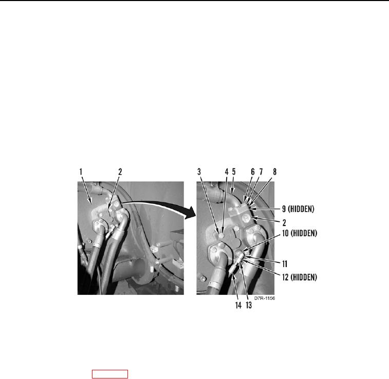
4. Install manifold (Figure 4, Item 2), four washers (Figure 4, Item 4), and bolts (Figure 4, Item 3) on chassis
(Figure 4, Item 1).
5. Install O-ring (Figure 4, Item 10) and fitting (Figure 4, Item 11) on manifold (Figure 4, Item 2).
6. Install new O-ring (Figure 4, Item 12) on fitting (Figure 1, Item 11).
7. Install hose (Figure 4, Item 14) and tube nut (Figure 4, Item 13) on manifold (Figure 4, Item 2).
8. Install three new O-rings (Figure 4, Item 9) on hoses (Figure 4, Item 5).
9. Install 3 hoses (Figure 4, Item 5), 6 flanges (Figure 4, Item 8), 12 washers (Figure 4, Item 7), and bolts
(Figure 4, Item 6) on manifold (Figure 4, Item 2).
Figure 4. Manifold.
0119
END OF TASK
FOLLOW-ON TASKS
000119
1. Install transmission oil (WP 0151).
2. Verify correct operation of machine (TM 5-2410-241-10).
END OF TASK
END OF WORK PACKAGE