
TM 5-2410-241-23-2
0120
INSTALLATION
000120
N OT E
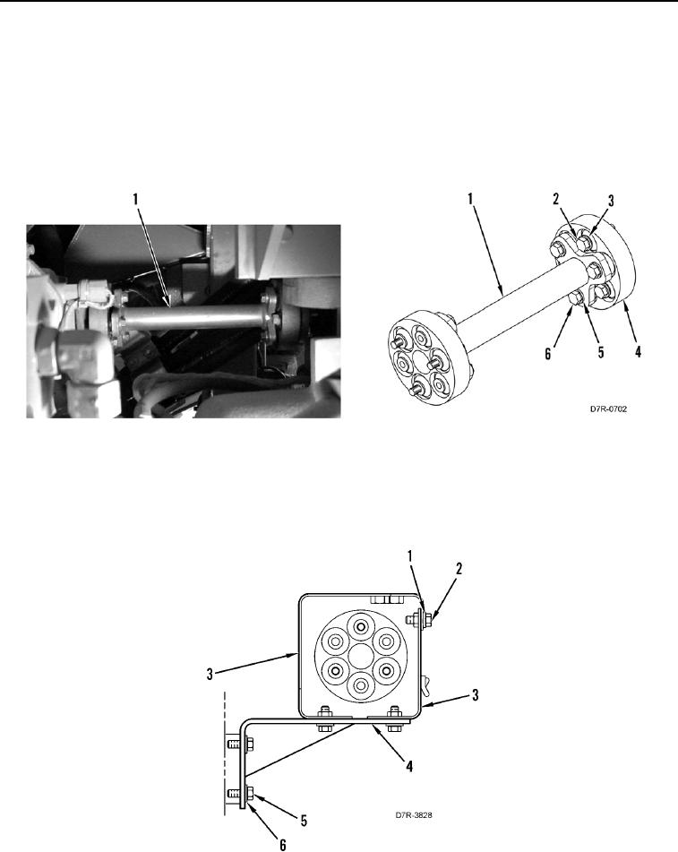
Install bolts as noted during removal.
1. Install two couplings (Figure 5, Item 4), six washers (Figure 5, Item 5), and bolts (Figure 5, Item 6) on shaft
(Figure 5, Item 1).
2. Install shaft (Figure 5, Item 1), six washers (Figure 5, Item 3), and bolts (Figure 5, Item 2) on machine.
Figure 5. Couplings.
0120
3. Install bracket (Figure 6, Item 4), four washers (Figure 6, Item 6), and bolts (Figure 6, Item 5) on machine.
4. Install two guards (Figure 6, Item 3), six washers (Figure 6, Item 1), and bolts (Figure 6, Item 2) on bracket
(Figure 6, Item 4).
Figure 6. Guards.
0120